Specification
The Bread Modular system specification is straightforward. The following aspects are defined:
- Power Voltage Requirements
- Audio/Signal Voltage Levels and Impedance Levels
- Physical Dimensions
Users can customize other aspects as required. Being open source, creating a custom module is as simple as downloading a sample KiCad project and modifying it.
Power Voltage Requirements
All modules must operate using a 3.3V power supply and a common ground. We chose 3.3V because it is very easy to get a regulated 3.3V from a USB power supply. This enables us to use Bread Modular virtually anywhere.
Audio Signal Specifications
The audio signal should oscillate around 1.65V with an ideal RMS of 2V (operating range: 0.65V to 2.65V). Square wave signals may utilize the full voltage range, from 0V to 3.3V.
Impedance Requirements:
- Maximum output impedance: 1kΩ.
- Minimum input impedance: 100kΩ.
The use of a common ground requires only a single cable for signal transmission.
CV/Gate Signal Specifications
Control Voltage (CV) & Gate signals must operate across the full voltage range of 0V to 3.3V.
Impedance Requirements:
- Output impedance: 1kΩ.
- Minimum input impedance: 100kΩ.
As with audio signals, the use of a common ground requires only a single cable for transmission.
Physical Dimensions
Modules are designed to draw power directly from breadboard rails. The top positive rail supplies 3.3V, while the bottom positive rail is connected to ground. Two 5-pin arrays with a standard 2.54mm spacing are used for these connections.
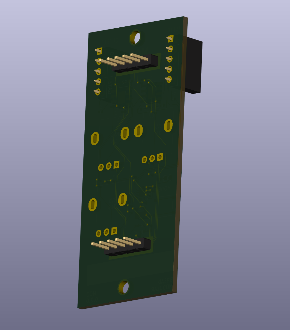
Modules must include two mounting holes supporting M3 screws — one at the top and one at the bottom of the PCB. Refer PCB designs for exact dimensions.
Each module must adhere to a minimum dimension (1B) defined in the specifications. (refer to the blank module KiCad files for dimensions).
Larger modules can be designed as multiples of this base dimension. Refer to the provided KiCad PCB design files or Gerber files for precise measurements.
Input/Output Specifications
The system's use of a common ground allows for single-cable connections for both input and output.
There is no mandatory placement for input/output sockets, but we recommend placing them on the top left and top right corners as illustrated above.
Modules should accommodate breadboard jumper cables with mating pins of 0.76mm and use appropriately sized sockets.
Refer to the "Common Parts" section for recommendations on socket components.
Component Placement Guidelines
- SMT Components: Use surface-mount components to optimize space.
- THT Components: Prefer through-hole components for input-related parts (see the "Common Parts" section).
Components can be placed on both sides of the PCB. Certain built-in modules utilize the back side for larger components, such as Vactrols. However, placing components on the back side may prevent the module from fitting into a breadboard, necessitating the use of a base module.
Sample Design Files
Use the following KiCad files designed according to the specification. Use them as the initial design for your modules.